The origin of the word “plasma” is attributed to two English physicists, Tonks and Langmuir, to designate an ionised gas (they were studying gas discharges during the 1920s). Since then, interest for this discipline has grown considerably as the multiple uses of plasmas were discovered, both in fundamental research (astrophysics) and in industry (surface coating, welding, flat screens and so on). Plasma physics thus developed, integrating all the breakthroughs in modern physics. It is a complex science, with its roots in many concepts used to describe solids, liquids or gases, yet calling on practically all the fields in physics (electrodynamics, statistical mechanics, quantum mechanics, collision theory, molecular and atomic physics, nuclear physics, kinetic theory, transport equations, thermodynamics, wave propagation, radiation, spectroscopy and so on), all of this generally resulting in coupled non-linear equations, difficult to work out even with today’s numerical techniques.
In addition to many technological challenges (components capable of withstanding intense heat, superconducting magnets, remote handling and so on), thermonuclear fusion poses huge theoretical difficulties, and has given birth to a particularly active branch of plasma physics.
The goal of controlled thermonuclear fusion research is to produce energy by efficiently confining a sufficiently hot and dense plasma. Start then by learning about Lawson’s criterion, fixing the conditions in which energy may be produced from a fusion plasma. The questions which come up may thus be summarised in the following way:
How may the plasma particles be confined effectively?
This is the main problem of magnetic confinement and of heat and particles transport.
How may the temperatures required for the future reactor be attained?
This is the main problem of plasma heating, which also enables current generation in the machine.
How may the components of the plasma vacuum chamber, and therefore the plasma from impurities emitted by the surrounding walls, be protected?
This is the main problem of plasma wall interaction and particles and heat extraction, with the original solution from Tore Supra: the ergodic divertor concept.
Finally, it is impossible to answer all these questions without possessing well-adapted measurement devices to analyse what happens in the heart of the tokamak. These are the diagnostics.
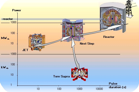
Tore Supra, the only large machine in the world capable of obtaining long pulses thanks to its supra-conducting magnets, offers physicists the unique opportunity of handling these problems with a view to steady-state operation, indispensable to the future reactor. This is the speciality of Tore Supra: long pulses.
How can we trigger multiple fusion reactions ? It is necessary to confine effectively enough a sufficiently dense and hot plasma. Why? Here are the explanations
a. Plasma power balance
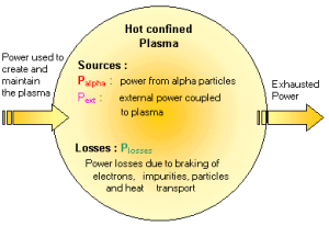
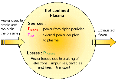
As in the example of a cauldron, the plasma energy balance is determined by the energy sources feeding the plasma and the energy losses cooling it down. For the plasma to remain stationary (i.e. not changing over time), the energy balance must be in equilibrium, i.e. the sources must compensate the losses.
Energy sources : Pfusion and Pexternal
Fusion power : Pfusion :
The total power produced by the D-T fusion reaction Pfusion is divided between the products of the reaction, the alpha particles, i.e. the helium nuclei (He), and the neutrons. This gives:
Pfusion = Palpha + Pneut
The neutrons take away about 80% of the energy, while the heavier alpha particles, keep about 20%. But this energy does not end up in the same place :
Palpha the main source of the plasma energy comes from the alpha particles. Indeed, these charged particles are confined by the tokamak magnetic field, and give their energy to the plasma by collision.
Pneut in contrast, the neutrons (n) from the fusion reaction are not sensitive to the magnetic field, since they have no charge, and thus escape quickly, without having time to give their energy to the plasma. They are stopped by the materials in the components surrounding the tokamak vacuum chamber.
External power Pexternal :
If the energy from the fusion reactions is not sufficient to compensate losses, it is necessary to supply energy from the outside to maintain the plasma using an additional heating system. This is the external power Pexternal
Energy losses : Plosses
The plasma confinement by the magnetic field is not perfect: particles and heat diffuse from the plasma center towards the outside. The losses connected to this particles and heat transport are considerable.
As a hot body, the plasma also cools by radiation according to different processes. The electrons emit continuous radiation in their collisions with ions (“Bremsstrahlung”). They also emit synchrotron radiation due to their gyration movement around field lines, which may grow considerably when the plasma is heated up to a very high temperature. Finally, the impurities emitted by the wall surrounding the vacuum chamber produce line radiation due to the different atomic physic processes which have taken place in the plasma. This contribution may become very important if the plasma is strongly polluted and may even lead to an abrupt loss of plasma confinement: this is known as a disruption.
The result of all these terms gives the total power lost by the plasma Plosses
The balance
The temporal variation of the plasma energy W may thus be written as : dW/dt = Palpha + Pexternal – Plosses
Reminder: only the alpha particles give their energy to the plasma, the rest of the fusion power is dissipated into the components surrounding the plasma.
If the source term is higher than the loss term (dW/dt >0), the plasma gains energy;in the opposite case (dW/dt < 0 ), it loses it. If the sources precisely compensate the losses (dW/dt = 0), the plasma is stationary. Several useful quantities may now be defined.
The energy confinement time tE
This is the characteristic time of decrease in plasma energy; in other words, it is the time taken by the plasma to empty itself of its energy content if the sources supplying it are abruptly cut off. Thus:
W/ tE= Plosses
NB : this time has nothing to do with the pulse duration, which is determined by the capacities of the machine magnetic system or plasma instabilities. For example, on Tore Supra, the energy confinement time is around 200 milliseconds (or 0,2 seconds) while the pulses last tens of seconds and even minutes
The amplification factor Q
This is the ratio between the power from fusion reactions and the external power supplied to the plasma by the heating systems:
Q = Pfusion / Pexternal
This figure thus qualifies the plasma’s energy balance. If it is higher than 1, more energy has been produced with fusion reactions than was necessary to supply to maintain the plasma.
NB : the Q factor must not be confused with the overall efficiency of the installation.
The Break-even
This is the situation corresponding to Q = 1, i.e. the moment when the quantity of energy produced by the fusion reactions is equal to that supplied to maintain the plasma ( Pfusion= Pexternal) . This is an interesting stage from the scientific point of view, as heating of the plasma is then to a great extent done by the alpha particles and no longer nearly solely by the additional heating, which is close to the situation of the reactor.
Ignition
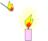
This is the situation where the power supplied by the fusion reactions is enough on its own to compensate losses ( Palpha= Plosses ) and where the external power can thus be switched off. This corresponds to an infinite Q amplification factor ( Pexternal = 0). The plasma is thus self-maintained like a candle, which, once it has been ignited by a match (external power), carries on fuelling itself.
Most current experimental machines destined for research and not yet for electricity production, operate at Q<1, i.e. the plasma consumes more energy than it supplies. They only use deuterium as a fuel, enabling the necessary physical studies without the use of radioactive tritium; the results obtained in D-D fusion to D-T fusion are then extrapolated. Only 2 machines have for the moment experimented with the use of tritium: the American machine TFTR, now closed, and the European machine JET, which holds the world record of fusion power in D-T, with 16 MegaWatts produced, corresponding to an amplification factor of 0.64.
Energy balance and Lawson criterion
Let us put the plasma energy balance into terms of the plasma physical parameters. This is called Lawson criterion. The three keys to the success of a fusion machine follow from it; confinement efficiency, density and plasma temperature.
b. Lawson criterion
Let us go back to our energy balance. At stationary state (dW/dt = 0) , we have :
Palpha + Pexternal = Plosses = W/ tE
By replacing Pexternal by Pfusion /Q and by using the fact that the plasma energy W and fusion power Pfusion depend on density n (i.e. the number of particles per unit of volume) and temperature T of the plasma, we obtain a relation expressing the constraints on the plasma parameters (density, temperature confinement time of the energy) if we want to obtain a pulse with a given amplification factor Q. This is what is called the Lawson criterion, which gives the value of the product of plasma density multiplied by the energy confinement time tE at a plasma temperature T to attain an amplification factor Q. How about a little proof for mathematicians? Click here.
In practical terms, for a reactor conditions, we obtain :
n T tE > 1021 (keV m-3 s) with T between 10 to 20 keV
In other words, to be able to produce energy from fusion reactions, a sufficiently hot (T) and dense (n) plasma must be confined effectively ( tE , not to be confused once again with pulse duration) * .
* NB : in the following, we will look at fusion by magnetic confinement, which works at relatively low densities, while trying to obtain long confinement times. There is however possibility, inertial confinement (bombarding a solid deuterium and tritium target with laser beams or very intense particle beams) operating at very high densities (matter compressed by the beams) with very short times.
The difficulty resides in obtaining the three parameters simultaneously. Indeed, for example, when we increase the density (n) by injecting gas into the machine or the temperature T by adding additional power to the plasma, the confinement (tE) of a tokamak tends to deteriorate.
In a tokamak, achievable plasma densities (i.e. the number of particles per unit of volume) are around 1020 per cubic metre (m-3); this is in fact very low, much lower than the density of the air surrounding us, and corresponds to conditions near to that of a vacuum. It is not possible to go any further, on account of the appearance of instabilities beyond a certain density threshold, the pressure exerted by the plasma becoming higher than that of the magnetic field. Emphasis is rather on the confinement time tE , which we try to take further than a second by developing complex physics scenarios (performances attained for the moment are no higher than 0,8 seconds).
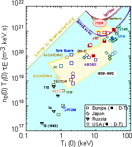
Progress in fusion research is illustrated by the increase in the triple product n T tE , which may be seen on the figure opposite and which has increased threefold since the first experiments at the end of the 60s up to the current machines (e.g. JET in Europe, TFTR in the United States and JT60U in Japan), closely approaching break-even. There remains only a factor of ten to achieve in order to reach the domain of the reactor.
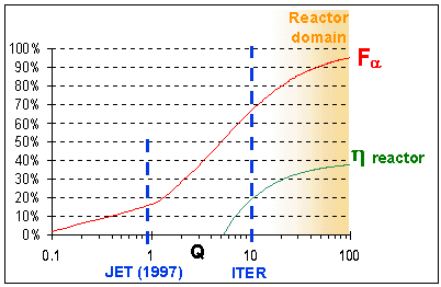
The next generation machine, ITER, intended to demonstrate the scientific and technical feasibility of controlled thermonuclear fusion, has been scaled up to attain an amplification factor of 10. The possibility of attaining ignition in certain physics scenarios has not been ruled out. This international project, launched at the end of the 80s, initially with four partners (Europe, Japan, the United States and Russia), has entered the final phase of dimensioning. Now with three partners (Europe, Japan and Russia), it is awaiting the decision for building, with in particular the choice of a site in one of the partner countries. Studies are in progress to assess the potential of Cadarache as a European site candidate.
It is worth noting that the future reactor does not need to be at ignition (infinite amplification factor Q) to work, but simply to reach a Q factor sufficient for the global efficiency ηreactor of the power station to be worthwhile, taking into account the conversion of thermal energy into electricity by conventional methods (turbine etc) and the fact that a part of the energy produced is reused to supply the additional heating systems needed to maintain the plasma.
Typical figures for a reactor are amplification factors of several tens, corresponding to a global reactor efficiency ηreactor of 35 % and a fraction of plasma heating by alphas Fα of 90% (i.e. 10 % of the remaining heating is provided by the additional heating systems).
How do we bring together particles that at first sight have no reason to stay together? In the sun, gravitation takes care of it. On earth, we use powerful magnetic fields.
a. Particle trajectories
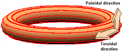
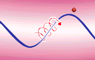
Plasma confinement in a tokamak is based on the property that charged particles have of describing a helical trajectory around magnetic field line. Look at the movement of a charged particle around a right magnetic field line.
The particle, represented in blue, describes a helical movement around the magnetic field line, which follows the guide centre of the trajectory, represented in green.
The gyration radius of the particle, called Larmor radius, depends on the intensity of the magnetic field, the mass and charge of the particle and its energy. The stronger the magnetic field, the smaller the Larmor radius, the particle staying “stuck” near the field line. Moreover, the electrons, much lighter than the ions, have a much smaller Larmor radius for the same energy. Finally, very energetic particles have a much larger Larmor radius than low energy particles, and are therefore more difficult to confine. The Larmor radius may typically vary from several millimetres for not very energetic particles with an intense magnetic field to tens of centimetres for very energetic particles.
The confinment solution thus consists in closing the magnetic field line on itself to trap the particle, as you may see below.
We are now in a configuration where the path of the magnetic field is solely toroidal.
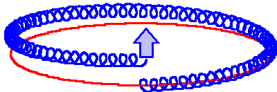
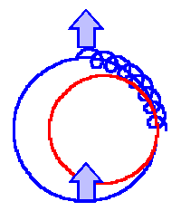
Unfortunately, on a simple circular trajectory of this type, the particle undergoes a slow cross drift, due to the drift gradient of the magnetic field and centrifugal force, depending on the sign of its charge. For example, the ions will drift up (as illustrated on the diagram opposite) and the electrons down.
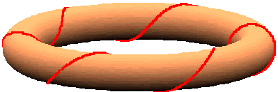
To compensate this effect, the idea is to stabilise the configuration by adding a poloidal component to the toroidal magnetic field. This is the magnetic configuration used in the tokamak.
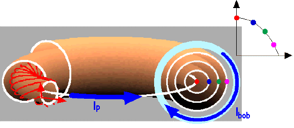
The field lines become helixes twisted round stacked toric surfaces, called magnetic surfaces.
The particle then spends half its time head upwards, where the vertical drift, which we suppose to be towards the top as in the example opposite, moves it away from the magnetic surface, and the other half head down, where the vertical drift pulls it back to the magnetic surface. The drift effect is thus on average compensated.
In a tokamak, the toroidal magnetic field is produced by external coils, whereas the poloidal magnetic field is induced by a current flowing toroidally in the plasma . This current is generated by transformer effect, from a primary circuit of which the secondary is the plasma. Tore Supra is outstanding in being equipped with supra-conducting magnets, which enable it to guarantee a permanent toroidal field (the machines equipped with conventional magnets are limited in duration by heating of the copper coils). The pulse duration is thus limited by the capacity of the primary circuit generating the plasma current inducting the poloidal field.
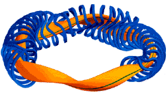
Finally, there exists another configuration, called a stellarator retour, in which the magnetic field is provided completely by external toroidal as well as poloidal coils. The fact of not having an intense current flowing in the plasma is an advantage in the event of plasma disruption, but the drawback is the complexity of the necessary magnetic coils. This may be seen on the diagram of the German stellarator project W7X Site de l’IPP : W7X , where the coils are represented in blue and the plasma in orange
The pitch of the helix on each magnetic surface is called safety factor (that is the number of large toroidal turns necessary to complete 1 small poloidal turn). In a tokamak configuration this safety factor typically varies from 1 in the centre of the plasma to several units on the edge. It is worth noting that, in general, if we follow the field line, it will entirely describe the magnetic surface around which it winds in the course of its successive journeys. This is true except in the case of a rational safety factor (i.e. equal to the ratio of two whole numbers). In this special case, the field line closes in on itself after a whole number of turns, resulting in specific properties for this (local modification of transport, triggering of instabilities, and so on)
Finally, we should note that in a first approximation, the macroscopic features (density, temperature, pressure and so on) are homogenous on a magnetic surface. We may thus describe them in a poloidal section simply as functions the plasma radius, for example by taking their value on each white circle showing a magnetic surface in the figure below. We talk in terms of radial profile (only depending on the radius), which for density, temperature and pressure is maximum in the centre of the plasma, decreasing towards the edge of the plasma, as illustrated on the figure below.
Magnetic confinement
The magnetic trap that confines the particles is not so easy to achieve: the plasma does not like it and tries to counter the magnetic field imposed on it…
b. Stability of confinement
Thanks to the tokamak configuration, we manage to confine the particles by compensating the pressure of the plasma, which tries to spread like a gas, by magnetic pressure. Unfortunately, such equilibrium, if quite easy to achieve, may become unstable, i.e. a small disturbance is likely to grow over time and, in certain cases, lead to total loss of confinement: this is what we call disruption. In other cases, it is just a partial loss of confinement, which does not result in the sudden shutdown of the pulse, but which considerably degrades its performance.
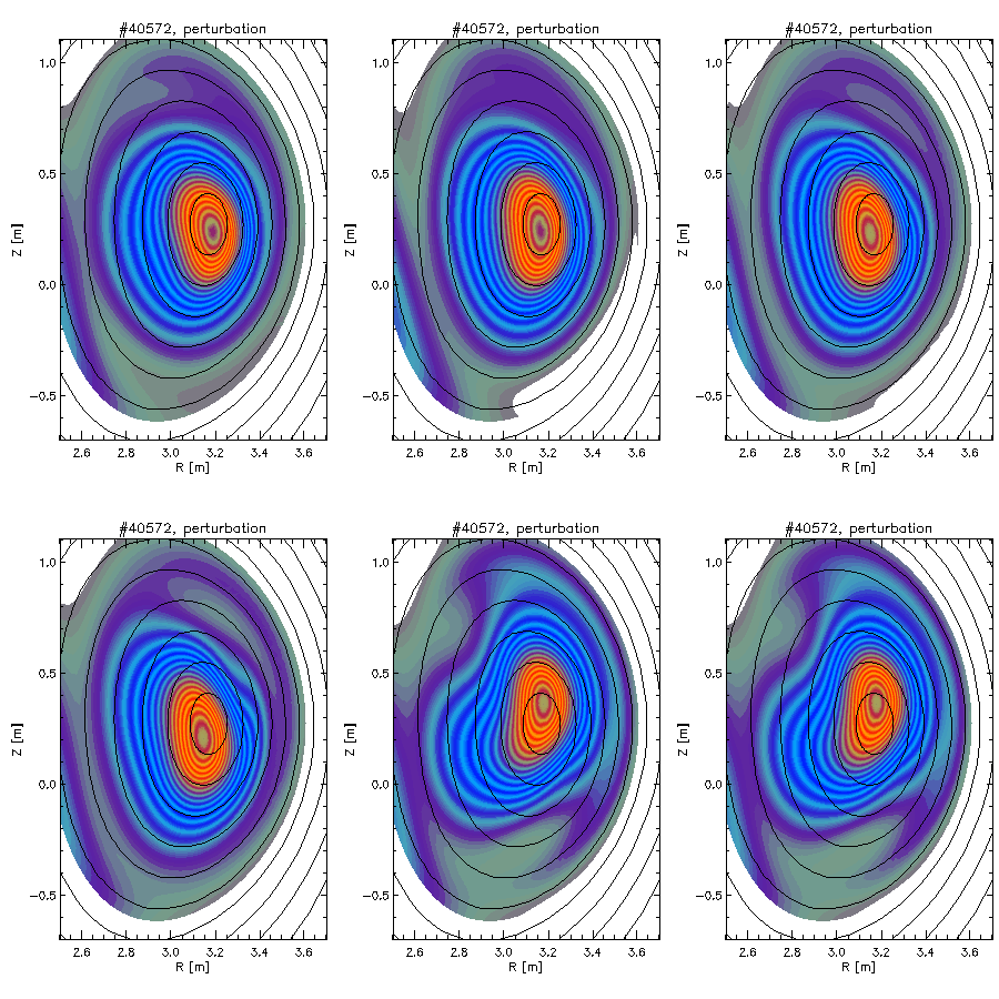
For example, we see here experimentally the image of a magnetic equilibrium perturbation on JET. The flow surfaces seen by X ray imaging should match the theoretical flow surfaces (in black on the figure), as is the case at the start of the demonstration opposite. But a state of instability develops, and disturbs the arrangement in the magnetic configuration. This ends up in a disruption…
Disruptions
A disruption may have many consequences. Any sudden decrease in current and/or magnetic fields induces mirror currents and /or magnetic fields in the components around the machine. These components are then subjected to what may be considerable forces. The higher the initial plasma current, (and we often count in Mega Amperes in the tokamaks) the shorter time it takes to disappear; the more sudden the current variation, the more serious the disruption is. Tokamaks are thus designed to be able to withstand such events (we use non-magnetic materials, the structure of the machine is very robust, the different parts in contact are electrically insulated and the components are carefully attached inside the chamber). Apart from these mechanical forces, all the energy contained in the plasma is also transferred over a short time to the components of the vacuum chamber, which are thus designed to withstand these extreme peaks of heat. Finally, disruption also has consequences on the experimental programme. It is generally difficult to restart the machine directly after a disruption, and it is often necessary to resort to conditioning pulses before being able to resume experimentation. Even if disruptions are still a part of everyday life of present tokamaks, which are still at the stage of being research instruments, it is clear that there is an interest in trying to avoid them, particularly by studying the stability of magnetic equilibria
Instabilities
The study of stability of magnetic equilibria is called magneto-hydro-dynamics (MHD for the initiated). This complex name simply covers the notion of fluid (hydro) in movement(dynamics) in a magnetic field (magneto), which applies very exactly to what happens inside a tokamak. To want to confine a hot plasma in an immaterial container formed by the magnetic field lines is a bit like wanting to contain a gas under pressure in a tyre inner tube. Another comparison, which we often hear from physicists to show the difficulty, is to a ring of jam (graphic representation of the plasma) that must be confined by using sticky tape. More seriously, by going back to the image of a tyre inner tube, MHD helps to optimisetube characterisation (geometry, rubber thickness) so that it will withstand the gas pressure without bursting, leaking or kinking. We will call β the ratio of the plasma kinetic pressure (proportional to its density and temperature) to the confinement magnetic pressure (proportional to the intensity of the magnetic field). For the ” inner tube ” not to burst, the magnetic confinement must be stronger than the plasma pressure forces , i.e. the ratio must be smaller than 1. Practically, we find that this limit in b is much lower than 1, of the order of few percentage, because of the appearance of instabilities. This notably limits the maximum density that may be obtained, since the plasma kinetic pressure is directly proportional to it.
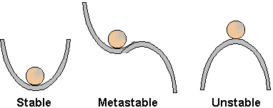
To understand the notion of equilibrium stability, the simplest analogy is that of a marble rolling on a corrugated surface. Depending on the geometry of the surface, the equilibrium of the marble will be stable, meta-stable or unstable, as shown below.
The mechanisms of instability in plasma physics are nearly unlimited. Some instabilities are comparable to examples borrowed from fluid mechanics, as the Rayleigh Taylor’s instability, which consists of superposing two fluids with the heaviest on top. Imagine for example a vessel in which you pour water and then carefully add oil over the top. The system is then in a state of meta-stable equilibrium. The slightest nudge will provoke a change with the heavier fluid dropping to the bottom, which corresponds to a stable equilibrium.
Another type of instability are kink instabilities, which occur when a current parallel to the magnetic field cause twisting of the filed lines, recalling the effect obtained if we twist a rope too much: the rope twists out and kinks. Other instabilities are really proper to plasma physiscs and have no equivalent in other domains.
Magnetic confinement
How do we bring together particles that at first sight have no reason to stay together? In the sun, gravitation takes care of it. On earth, we use powerful magnetic fields.
c. Particles and heat transport
Once a stable magnetic equilibrium has been established, we have seen that the particles, when they are considered individually, follow the magnetic field lines, if the Larmor radius and drift movements are neglected. However, they undergo other phenomena, which will change this simple image and result in rather more complex transport mechanisms, which may be divided into two major categories:
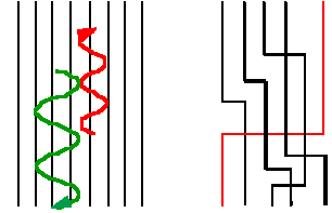
neoclassical transport :the effects of collisions between particles, which will make them deviate from their initial trajectory in a sort of random walk, giving rise to radial diffusion when they “jump” from one magnetic surface to another, because of the shock. This is called neoclassical transport.
We can then modify the simple image of the particle following its field line as on the diagram on the left by the image of a succession of jumps from one field line to another, as illustrated on the right hand diagram.
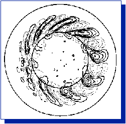
“anomalous” transport :the effects of turbulence, i.e. magnetic and electric fields fluctuations, give rise to the propagation of waves in the plasma. This results in an increase in the heat and particles transport. This transport called “anoumalous”, has resulted in significant theoretical developments If linear theory is now well-established and helps forecast the conditions in which a wave becomes unstable, it is not valid when a wave increases, and we must then turn on to more complex non-linear models to simulate the development of the instability.
Heat transport is a phenomenon quite comparable to particle transport. First of all, diffusing particles carry their own energy : this is the phenomenon of convection. Then collisions allow particles to exchange energy: this is thermal conduction
This diffusion phenomenon from inside plasma towards the outside tends to ” empty ” the plasma of its content in particles and energy, and determines the confinement machine performance. The diffusion of particles is characterised by a coefficient of proportionality, called diffusion coefficient, between the particles flow and the density gradient. Similarly, for heat, the diffusion coefficient is defined by the ratio between the heat flow and the temperature gradient. The larger this coefficient, the greater the diffusion, and the worse the confinement.
Experimentally, we observe much greater losses of energy (and therefore a much shorter time of confinement) than those predicted by neoclassical transport alone. Anoumalous transport would seem to be the dominant term. Many studies are underway to refine the comprehension of phenomena likely to explain this transport. In particular, we are trying to establish the dependence of the diffusion coefficient on the machine and plasma parameters. Two types of behaviour have been identified:
Bohm behaviour: the diffusion coefficient does not depend on the size of the machine (and thus nothing is gained by going up to a large scale reactor)
Gyrobohm behaviour: the diffusion coefficient depends favourably on the size of the machine (and therefore a considerable gain is achieved in going on to the reactor)
The trends arising from the latest studies are that behaviour is different according to the specie under consideration (electrons or ions) and confinement mode :
electrons are Gyrobohm-type whatever the mode of confinement
ions are Bohm-type in the normal confinement mode, and become Gyrobhom when put in the enhanced confinement mode.
Magnetic confinement
As the plasma does not seem to want to cooperate, physicists have come up with scenarios where we create a transport barrier in the plasma, to retain the particles in its centre and obtain a more effective confinement. Today, the H mode, an operating mode with good confinement and a reference for machines of the next generation, is solidly established, and research is well underway on alternative scenarios of called “advanced tokamaks”.
d. Modes of confinement
As the theoretical comprehension of radial diffusion phenomena remains limited, many experimental studies on confinement have been carried out in the major machines worldwide. This has led to a very great database being compiled, from which empiric laws have been determined, expressing confinement time as a function of the main machine and plasma parameters, rather like the way that we resorted in wind tunnel studies to establish some laws of fluid mechanics. This is of crucial importance to be able to extrapolate the performance in confinement to a next generation machine.
The first scaling law of this type, established in ohmic operation, i.e. without additional power, showed in particular an increase in confinement time with the major radius of the machine. Operation with additional power, indispensable to raise the plasma temperature to the necessary conditions for the future reactor, was then studied. It was found that the confinement deteriorated compared to the values when the power coupled to the plasma was increased.
The H mode
Nevertheless, it was noticed that under certain conditions, confinement was abruptly improved above a power threshold but still not as good as in ohmic operation. This enhanced confinement was called H mode (for “High confinement”) in contrast to the confinement mode obtained below the power threshold, called L mode (for “Low confinement”). It enables improvement of confinement times by a factor of nearly 2 in comparison with L mode. The discovery of this mode of enhanced confinement, on the ASDEX machine in the eighties, was crucial to thermonuclear fusion, and the H mode is still today the reference scenario for the next step machine ITER.
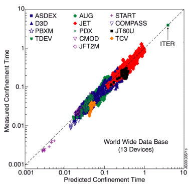
You see opposite the database used in establishing the scaling rule for confinement time in H mode, showing the agreement between experimental results from the different machines (in ordinates) and the result of the scaling law of scale (in abscissa).
This empiric law forecosts:
an increase of confinement time with the machine major radius and the plasma current (which explains in part why JET, the largest of present machines, obtains the best performance)
deterioration with additional power coupled to the plasma
For the next generation tokamak ITER, an extrapolation based on the scaling law established from results on present machines predicts a confinement time around 5 secs, which will permit to attain the goals fixed for the project (amplification factor Q=10) . It is worth noting that the threshold power at the transition from L mode to H mode depends, amongst other things, on the size of the machine, resulting in a very large figure in the case of ITER.
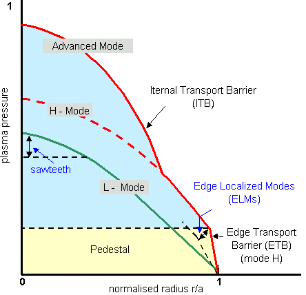
The stabilising mechanisms, enabling the transition to H mode have not been completely elucidated and are the subject of a number of both theoretical and experimental studies. If the H mode was originally found by accident, we know today that stabilisation of turbulence, which is the cause of confinement deterioration, is obtained thanks to a differential in the poloidal rotation velocity of the different magnetic surfaces (the fact that rotation velocity varies greatly from one surface to another is called velocity shear). Indeed, the magnetic surfaces are in rotation under the influence of the plasma electric fields. A modification of these electric fields causes velocity shear, preventing turbulence from developing. A transport barrier is set up at the plasma edge, retaining heat and particles in its core. The most characteristic point of these scenarios is the appearance of strong gradients in the plasma edge, leading notably to the creation of a pressure pedestal in the plasma, proportional to its density and temperature. The red curve representing the H mode on the drawing below is steeper in the edge zone than in the corresponding green curve in L mode.
Nevertheless, let us not imagine that the situation is calm: these very steep gradients at the edge lead to specific instabilities in the H mode, which we call ELMs (for Edge Localised Modes). The plasma pressure profile relaxes periodically towards less steep slopes (black dotted line under the red curve on the diagram). Then the barrier rebuilds itself, the profile steepens again before collapsing at the following ELM. As a consequence, large particles and heat blasts escape from the plasma at each ELM, imposing strong constraints on vacuum chamber components.
The L mode is also not at rest, with instabilities in the centre called sawteeth (dotted line under the green curve in the centre): the central temperature drops abruptly when it reaches a limit, before rising gradually up to the next sawtooth where the phenomenon repeats itself. We now know, however, how to avoid sawteeth, due to many experimental and theoretical studies, working in the domains of plasma parameters (current, magnetic field, additional power) where the phenomenon does not occur. This is not yet the case for ELMs in H mode: the identification of the mechanisms leading to this phenomenon is a very active area of research.
Other enhanced modes of confinement
In addition to the H mode, there are other modes of enhanced confinement, and particularly at the end of the nineties we saw the rise of the called ” advanced tokamak ” scenarios, in which performance is achieved thanks to very delicate control of current and electric field profiles in the pulse, generating internal transport barriers (or ITB for Internal Transport Barriers) in a more control region than in the case of H mode, as we see on the diagram above. These scenarios, promising but difficult to implement on account of the retroaction to be carried out on the current profile, are still in the exploratory stage.
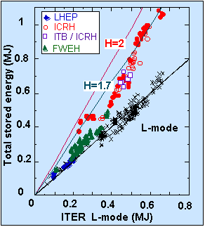
On Tore Supra, other modes of enhanced confinement involving internal transport barriers are being explored, as shown by the curve opposite. They are obtained by using specific heating scenarios, whose stabilising influence on the plasma diminishes transport phenomena. Confinement time can thus be increased up to a factor of 2 over L mode (see the H parameter, which translates confinement improvement compares to L mode). We have for example the LHEP modes (for Lower Hybrid Enhanced Performance) obtained with hybrid frequency heating, and other modes obtained with ion cyclotron frequency heating, used in ICRH mode (for Ion Cyclotron Resonant Heating) or FWEH (pour Fast Wave Electron Heating).
On other machines like Textor in Germany, another mode of improved confinement, RI mode (for Radiation Improved), was obtained by injecting well chosen impurities into the plasma, to benefit from another stabilising effect (density peaking). It allows to reach performances close to those of the H mode, while having the advantage of reducing the heat load on plasma facing components.
How do we achieve temperatures of the order of hundred million degrees, required for the operation of a fusion reactor? Easy, just switch on the heating…
a. Introduction
Lawson criterion, which expresses the constraints on plasma parameters to produce energy from thermonuclear fusion, requires a temperature of 10 to 20 keV . To achieve these very high temperatures (several hundred million degrees), it is necessary to heat the plasma.
Ohmic operation
The first natural heating mechanism is the Joule effect, associated with the current flowing in the plasma, necessary to create the tokamak magnetic configuration. Just as the filament of an electric bulb heats up when a current passes through it, the plasma will increase in temperature under the effect of strong current (in Mega Amperes). Unfortunately, this effect, proportional to the plasma resistance, which tends to collapse when the temperature increases, saturates and only enables limited temperatures to be reached (around 10 million degrees). This “natural” heating operation is called ohmic operation, in reference to the unit of measurement of electrical resistance, the ohm.
Additional heating
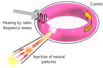
To reach the required temperatures, we thus resort to additional heating systems. These are classified into two main families :
heating by injection of highly energetic neutral particles, which consists of heating the plasma using the collisions between the very energetic injected particles and the plasma particles.
heating by radio-frequency waves, which consists of coupling to the plasma with a wave at a frequency chosen, so as to be in resonance with a category of particles in the plasma (i.e. at the same frequency) and therefore caoable of communicating energy to them, a bit like in a microwave oven which heats a dish by shaking up its water molecules.
Heating and current generation
How do we heat a plasma ? One solution is to inject a beam of very energetic particles, which give their energy to the plasma through collision.
b. Heating by injection of energetic particles
To obtain high-energy particles the technique is to use intense electrical fields to accelerate a beam of charged particles (deuterium ions). However, these charged particles cannot enter the tokamak as they are, since, if the magnetic configuration traps charged particles inside the machine, it also prevents charged particles from the outside from entering. We must thus neutralise the beam before injecting it into the discharge, hence the name of neutral injector given to the system. A neutral injector is therefore made up of three main parts :
an ion source
an accelerator
a neutraliser
To deposit their energy in the plasma core, the beam particles must be given a huge amount of energy. We can reach up to 100 keV with positive deuterium ions, but beyond this limit, the neutralisation stage gets very delicate, and negative deuterium ions must be used; they are more difficult to create at the level of the ion source but have a better neutralisation efficiency in order to reach the necessary MeV for the next generation ITER machine.
The injectors working with positive ions on current machines (JET for example) give huge powers to the plasma (20-30 MW), sufficient to cross the threshold enabling access to enhanced confinement mode (H mode). The tokamak Tore Supra is not fitted with neutral injection for plasma heating, which is carried out by radio-frequency wave systems. On the other hand, a neutral beam to be used for diagnostics , using the same basic principle but being less powerful, is in the course of development.
The Euratom-CEA Association has, in addition, several test benches dedicated to neutral beam development for next generation machines, particularly in the field of negative ions.
Heating and current generation
Electromagnetic waves are part of our everyday life, from the radio to the microwave oven. On Tore Supra, a new kind of microwave oven heats up the plasma…
c. Heating by radio-frequency wave
Just like in other fluids, like air or water,all kinds of waves CEA educational website can propagate inside a plasma. This is a large field in plasma physics, since there is a huge huge wealth of possibilities depending on the nature of the wave (its frequency, polarisation CEA educational website …) and on the plasma properties (density, temperature,…). Waves are generally speaking ranked by family according to frequency and propagationdirection relative to the magnetic field (parallel or perpendicular). Depending on the latter, the waves may either be propagative or evanescent, may be reflected or change polarisation, may change amplitude in the course of time or, quite the contrary, may transfer energy to the plasma. It is the latter that interests us here, and it is this property that we use to heat the plasma with electromagnetic waves with specifically selected characteristics.
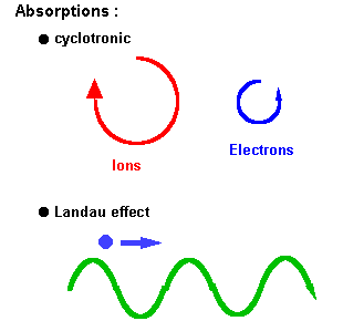
There are two main mechanisms enabling plasma to gain energy from a wave: cyclotron type absorption and Landau type absorption. In both cases, the wave-particle interaction is resonant, i.e. they vibrate at the same frequency.
In the case of cyclotron absorption, one couples to the plasma a wave at a frequency resonating at the rotation frequency of a species (ions or electrons) in their trajectory around the magnetic field lines.
In the case of Landau absorption, one couples to the plasma a wave in resonance with a population of particles, in such a way that the wave and particle nearly have the same velocity propagation. The situation is then more or less comparable to that of a surfer, moving at the same speed as the wave, and taking advantage of its speed.
Current generation
In addition to heating the plasma, waves also enable the generation of current. Indeed, in the tokamak configuration, a current flowing in the plasma is used to create the poloidal component of the confining magnetic field. This current is itself induced by the transformer effect in which the plasma is secondary, from a primary circuit that only has a limited capacity. When the primary circuit has been emptied, there is no more plasma current , and therefore no more poloidal magnetic field, thus no more confinement: it is the end of the discharge. On Tore Supra, whose toroidal magnetic field is provided by superconducting magnets and is therefore permanent, this is one of the main limitations of pulse duration (on the other tokamaks, where the toroidal magnetic field is produced using conventional copper magnets, the toroidal system is also a limitation). We see therefore the interest in plasma current generation by methods other than the transformer effect: this is what we call non-inductive current generation. This is a field which is very actively explored in Tore Supra, the tokamak specialised in long duration pulses.
To get from the heating effect to the current generation effect, an directionality effect has to be added to the wave spectrum, so that it only comes to resonate with particles having a preferential direction. A net impulse transfer is made in the toroidal direction, thus generating a current (since there are “more” charges flowing in one direction than the other in the toroidal direction; the outcome is therefore a current).
NB : we can also achieve current generation using heating by energetic particles injection, by directing the beam properly to transmit impulsion to the plasma particles in the toroidal direction.
The major families of radio requency heating
Three major families of heating exist, classified according to their range of frequency :
heating at the ion cyclotron frequency (FCI) : a few tens of MegaHertz (MHz )
heating at the hybrid frequenciy : a few GigaHertz (GHz)
heating at the electron cyclotron frequency (FCE) : about hundred GHz
Each type of heating has its own applications, and is capable of providing different results (heating or current generation) according to the way in which it is used.
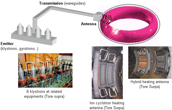
In any case, the wave is generated by different systems according to frequency (tetrodes or diacrodes for ion cyclotron frequency, klystrons for hybrid frequency, gyrotrons for electron cyclotron frequency), then is propagated to the tokamak by carefully scaled transmission lines (wave guides), and then is coupled to the plasma by means of an antenna, placed inside the vacuum chamber. Apart from the material problems posed by these sensitive electro-technical systems, the difficulty consists in coupling the wave to the plasma, involving complex physical processes and requiring proper control of the plasma edge.
Heating and current generation
The ion cyclotron wave, a versatile tool enabling access to the whole range of heating scenarios.
c.Heating by radio-frequency wave
Heating at the ion cyclotron frequency (FCI)
This heating system uses a fast wave which mainly propagates perpendicularly to the magnetic field surfaces at a frequency near to that of the gyration frequency of one of the ion populations (several tens of MHz , corresponding to wavelengths of a few decimetres). The gyration frequency depends on:
the mass of the ion in question, which helps in being selective with the ions that we want to excite,
but also the magnetic field whose intensity drops from the inside to the outside of the tokamak, enabling localisation of the place where we want to place the energy by adjusting the wave frequency.
Unfortunately, resonant cyclotron absorption is not possible on a plasma with a single ion component (screening effect). We then resort to a so-called minority ion cyclotron heating scenario, which consists in using a plasma with a majority of deuterium ions and a small percentage of hydrogen ions. We then adjust the frequency on the hydrogen, which has a lower mass than that of deuterium, and the wave is to a great extent absorbed by the hydrogen ions, whose energy increases by several hundred eV on each passage of their trajectory in the resonance zone. They then transmit their energy to electrons by collision, which in turn heat up the deuterium ions.
Several variations exist. We can choose to adjust the frequency to a multiple of the ion cyclotron frequency, described as harmonic cyclotron heating. In practice the second harmonic is used. When no ion species is in the minority, we can also use a so-called ion-ion hybrid resonance, where there is wave conversion to heat the electrons, described as heating by conversion mode.
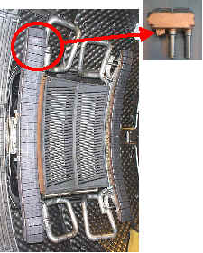
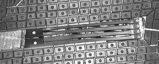
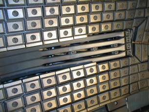
Here we see an FCI antenna in the Tore Supra vacuum chamber (median part), surrounded by two lateral protections sheltering it from the plasma. In close-up, a picture of the basic protection component, capable of withstanding the plasma heat load (several MW/m²). We also see the water pipes cooling the whole structure and the cellular protecting the inner vacuum vessel.
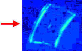
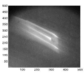
Finally, an infrared picture of the antenna in operation, showing the moderate heating of the protective lateral protections despite the plasma presence, thanks to efficient cooling.
Coupling the wave to the plasma remains a delicate point. The system must be finely adjusted to obtain the correct resonance. The antenna is a bit like the resonant part in an RLC type electric circuit, connecting the power source and the plasma. The plasma density in front of the antenna is critical. If it is too low, the wave cannot pass. The power is then reflected towards the transmitter instead of being transmitted to the plasma, which could be harmful. A security system surveys therefore the operation, and cuts the transmitter power in case of improper coupling. Other complex systems have been developed so that the antenna can adapt to small variations in density (on account of fluctuations linked to turbulence or loss of plasma control).
Heating and current generation
Hybrid frequency heating: the champion of current generation
c. Heating by radio-frequency wave
Heating at the hybrid frequency
By increasing the frequency, we reach the domain of the lower hybrid frequency, which uses a so-called slow wave of few GHz (corresponding to centimetre wavelengths, which thus are short compared to the plasma dimensions. The first use of this wave was to get into the conditions where the wave encounters the lower hybrid resonance in its journey through the plasma. This hybrid heating has turned out to be rather inefficient and is no longer used on present tokamaks.
On the other hand, the lower hybrid wave has a strong electric field parallel to the magnetic field, making it a good candidate to accelerate electrons in the toroidal direction by Landau absorption. We therefore use it in current generation mode, by phasing between the different waveguides going into the tokamak, so as to generate a wave with a dissymmetrical toroidal spectrum. The wave couples to the parallel movement of the electrons, more particularly of the very energetic electrons naturally present in a very small amount in the discharge. These supra-thermal electrons absorb it powerfully (so powerfully that the wave sometimes has trouble reaching the plasma core). The wave thus tends to develop this supra-thermal population : watch out for damage to plasma facing components, if it is not properly controlled. In addition, even if it is not absorbed too quickly, this type of wave has difficulty in propagating within plasmas that are very dense and hot. For these reasons, the hybrid wave is a good candidate for current generation in the peripheral region of reactor type plasmas. On the other hand, because of the direct and intense absorption by electrons, current generation efficiency (i.e. the quantity of current created per unit of power) of the hybrid wave is among the best.
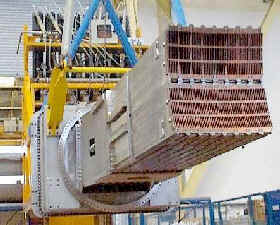
We see here a hybrid antenna (often called a grill) being handled before installation in Tore Supra.
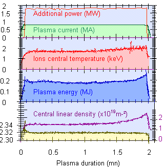
On Tore Supra, this heating system is extensively used for the non-inductive generation of current in the framework of the long duration discharge programme. It was with 2.3 MW hybrid power injected for 2 minutes into the machine that Tore Supra came to hold the world energy record of 280 MJ .As always, the crucial point is to ensure proper coupling of the wave to the plasma. In contrast to the FCI system, which needs operation above a critical density, the hybrid system is more efficient in generating current at low density.
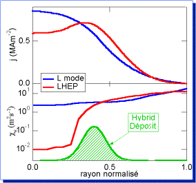
In addition, hybrid heating is used to go into enhanced confinement mode, LHEP (or Lower Hybrid Enhanced Performance) by shaping the current profile j inside the plasma. The current generated by the hybrid (in green here), located at half radius of the tokamak, comes in addition to the normal current, going from the current profile in blue of the L mode to that in red of the LHEP mode. The peak in current provokes an effect on the transport of particles and energy, as is seen on the heat transport coefficient ce, which collapses in the plasma centre in LHEP mode (in red) although it is relatively constant in L mode (in blue). This corresponds to a transport barrier, and enhanced confinement.
Heating and current generation
The electron cyclotron wave: a precision tool, putting power where we want it.
c. Heating by radio-frequency wave
Heating at the electron cyclotron frequency
This time we get to the scale of about hundred GHz for frequency, corresponding to millimetre wavelengths. Two modes of propagation are possible for this type of wave, which propagates perpendicularly to the magnetic surfaces: the O mode, which has an electric field parallel to the tokamak magnetic field, and the X mode, which has an electric field perpendicular to the tokamak magnetic field.
As in the case of ion cyclotron heating, the interaction takes place when the electron crosses a resonance layer, determined by the frequency used, and depending on the magnetic field. We may also use harmonic heating. The advantage of this type of heating is to produce very local deposits, and we use it as a precision tool to go and take energy to a well-targeted point of the plasma, which can have a stabilising effect on instabilities. In addition, in contrast to the two others, this mode of heating is less sensitive to edge conditions at the level of the highly simplified antenna, making coupling easier in a wider range of plasma parameters (the wave propagates even in a vacuum!). On the other hand, the power generator used (gyrotron) is more delicate to implement, above all on a long pulse, and Tore Supra is just starting experimentation with a new system adapted to stable operating conditions.
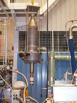
We see here an FCE heating power generator, under laboratory test..
We can also use this system to generate current, but as the mechanism is indirect, we cannot attain the efficiency attainable with the hybrid system.
Heating and current generation
Not content with holding the record for energy injected into a tokamak, Tore Supra is a contender for the GigaJoule…
d. The future : reaching for the stars with CIMES project…
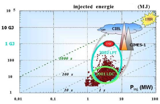
In pursuit of the long pulse, programme, in 2000 Tore Supra started an extension to its power injection system with the CIMES project( “Components for Injection of Matter and Stable Energy”) after upgrading its power extraction system with the CIEL project ( “Components Internal and Limiter”). The CIMES project, divided up into several phases, will ultimately attain, towards the year 2010, nearly 20 MW dof power coupled to the plasma in continuous operation (compared with tens of MW over 30 secs possible today with the heating systems, but limited to 10 secs by the capacities of heat extraction from plasma facing components in the machine before the CIEL project). The project includes, in addition, an improvement on the system of matter supply with a new injector of deuterium pellets.
Beyond the current record of 280 MJ of energy injected into the plasma held by Tore Supra (by coupling 2.3 MW of hybrid heating in addition to ohmic heating for 120 secs), we are proposing to reach the stage of 1 GJ at the beginning of the century, then ultimately twenty or so GJ, thus approaching the 200 GJ forecast for the machine of the next step in ITER.
Tore Supra offers here a unique opportunity to test out all components of different heating systems (generators, transmission lines, antennae) on long pulses, helping to guide our choice for the machines of the next generation.
Plasma-wall interaction and particles and heat extraction
As a result of diffusion out toward the plasma edge, the particles end up by leaving the magnetic trap: what happens when they encounter the wall ? What does the tokamak plasma edge look like?
a. Introduction
Despite the magnetic trap of the tokamak configuration, confinement of particles and energy in the plasma is not perfect, and heat and matter diffuse from the centre towards the outwards. This has the result of taking large quantities of energy and particles towards the plasma edge (with heat flows higher than those of the sun !). It is then up to the plasma facing components to simultaneously deal with both problems….
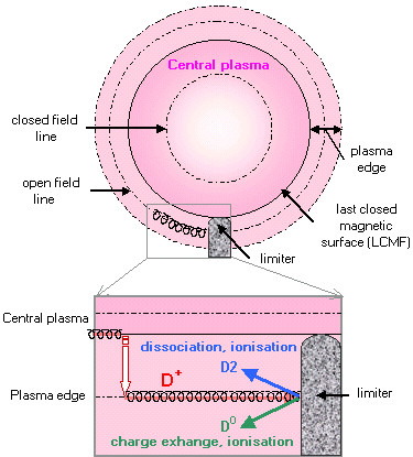
What does the magnetic configuration in the edge look like retour ? The difference with the central plasma, where the field lines are in a closed circuit, is that in this zone , the field lines are open, interrupted by a solid obstacle (the plasma facing component). The border magnetic surface between the two zones is called Last Closed Magnetic Surface (LCMF). retour This LCMF is defined by the first point of contact with a solid object, which thus limits the plasma, hence the name of limiter for components which are in the frontline facing the plasma.
The charged particles, whether they are in the central or edge zone, always follow the field lines and will therefore enter into collision with the solid body: this is what we call plasma-wall interactions. On collision, the charged particles neutralize (i.e. become atoms or molecules again by recovering electrons) and do not feef any more the magnetic field, and are therefore free to move in the course of collisions with plasma facing components or other particles, until they ionise once again in contact with the plasma. They then again start to follow the field lines, and may either supply the plasma with particles again if they have been ionised in the central zone of the discharge, or once again collide with a solid body if they have been ionised in the edge zone. This goes on until the particle has been taken out of the system, by being absorbed either by an wall, or by the external pumping system. We call all these phenomena recycling.
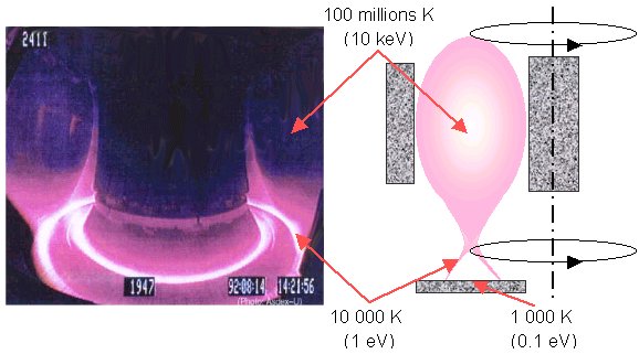
We thus witness an extraordinary encounter, where the fourth state of matter (plasma) meets the 3 others (solid wall, the gas resulting from the interaction of the plasma with the wall, and liquid, flowing a few centimetres below the surface of the wall to cool it down). We also go through a whole range of temperature, from hundred millions of degrees for the central plasma to 10,000 degrees for the edge plasma where the molecules and atoms are, and 1000 degrees for the surface temperature of plasma facing components.
We can see these three temperature zones on a picture of the tokamak Asdex IPP website : ASDEX taken by a visible CEA educational website light camera , where we see the edge plasma radiating strongly, while the central plasma, at a very high temperature, emits in a different range of wavelength (towards the X rays CEA educational website) and appears to be transparent to the camera.
Plasma-wall interaction and particles and heat extraction
The plasma attacks the wall by submitting it to intense heat and particles fluxes. The wall has its revenge on the plasma by emitting impurities which pollute it. What material can be found to reconcile the two adversaries?
b. The materials
It is by obtaining more and more performing plasmas that we have become aware of the importance of plasma-wall interactions. Indeed, in the first experiments, the duration of the pulse was too short to be able to observe significant heat or damage to plasma facing components. It was with the increase in power coupled to the plasma that we noticed that the wall, under bombardment from particles, emitted impurities (by erosion), like water gradually eroding the rock over which it flows. These impurities went on to pollute the central plasma and decrease the machine performance by radiating the energy coupled to the plasma, which is then lost instead of heating the discharge (see energy balance in a tokamak).
One of the first ideas was to change the wall material, and we then went from the first metal machines to components made of so-called light materials, like carbon or beryllium. Indeed, in addition to thermal properties, these materials have the advantage of radiating less strongly than metals when they are pulverised in the plasma. Thus, the Tore Supra tokamak inner vessel is largely covered with components made of carbon, a material also used for thermal shields in the space industry. In addition, original technologies of combining copper (cooling material) and carbon (plasma facing material) have been developed for the specific needs of Tore Supra, the only tokamak to operate with long pulses necessitating, as in the future reactor, the use of cooled components (i.e. criss-crossed by pressurised water circuits). These technologies have been implemented for the CIEL project, destined to improve the heat extraction capacity of Tore Supra.
NB : carbon also has other physical and chemical properties in terms of hydrogen retention and erosion in particular, which have major repercussions on plasma-wall interaction. The problems linked to retention of radioactive tritium in a reactor type machine mean that we are continuing to analyse alternative materials such as tungsten.
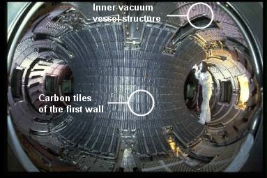
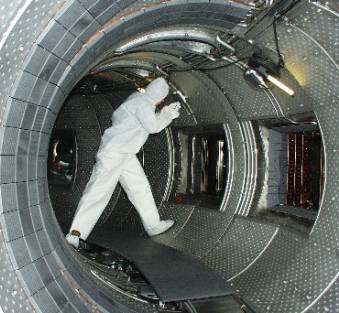
We see here, in the Tore Supra vacuum chamber, a welder working on the first innerl wall, made up of hundreds of carbon tiles. We can also see the cellular structure of the inner vessel, which has remained metallic, since the plasma is not in direct contact with it.
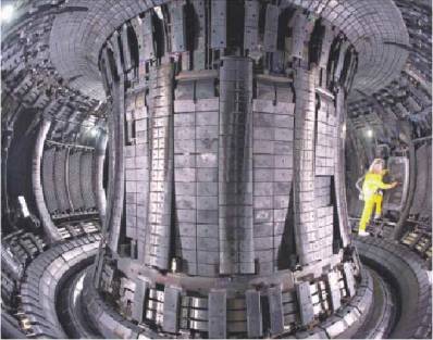
The JET JET website tokamak has, in addition to high flux carbon elements, a wall covered by beryllium. A protective suit must be worn inside the chamber on account of the toxic dust generated by beryllium.
Plasma-wall interaction and particles and heat extraction
How to prevent the plasma and the wall from causing each other mutual damage ? Physicists have developed several configurations to keep the central plasma away from the plasma-wall interaction region.
c. The different edge plasma configurations
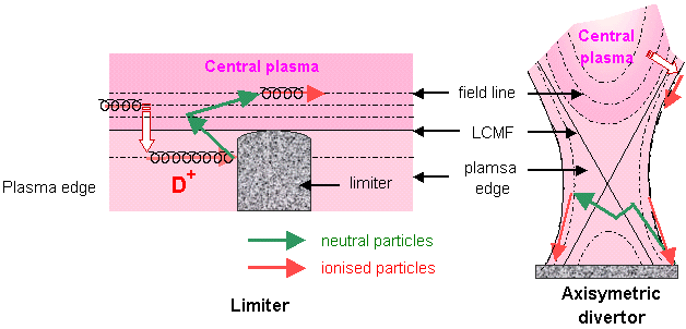
After optimisation of materials, a second idea was to push away the zone where plasma-wall interaction takes place, so as to avoid that impurities emitted in this zone reach the discharge core: this is the axisymetric divertor configuration, where the LCMF is no longer defined by the point of contact with a solid, as in the case of the limiter configuration, but by a “magnetic” frontier created by adding a coil around the tokamak.
We can see the advantage of the system on the figure below. The flow of particles leaving the plasma by radial diffusion is represented by the large white arrow with a red outline. In the first configuration, on the left, particles follow the field lines and meet the limiter (red arrow 1). These then neutralise, and may, on impact, tear impurities away from the wall, also in the form of neutrals. These neutral particles are not forced to follow the field lines (green arrow 2) and freely flow until they are again ionised by the plasma. Given the proximity of the central plasma, they are very likely to ionise again in the central plasma (red arrow 3). On the other hand, in the divertor configuration, on the right, the flow leaving the plasma is guided by following the field lines towards neutralisation plates far from the central plasma. The impurities are thus more likely to be ionised again in the edge zone, where they follow the field lines, to be once again intercepted by the neutralisation plates. They then remain in closed circuit without interfering with the central plasma: we then talk in terms of impurities screening. It is while testing this new configuration that the improved confinement H mode was discovered on the German machine Asdex during the eighties, which definitively ensured the success of this system. The largest present machines, like JET and JT60-U, are fitted with this type of device.
Ergodic divertor
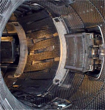
On Tore Supra, we have tested a variant of this configuration, the ergodic divertor, whose basic idea is the same – keep the plasma-wall interaction zone away from the central plasma – but using, to achieve this, a magnetic perturbation which “ergodises” the field lines at the edge of the machine, i.e. instead of a well-organised structure of stacked up tore, we obtain at the edge a chaotic mixture of field lines. The plasma-wall interaction is not kept away “geographically” but “magnetically” from the central zone. Here we come across the chaos concept, a fundamental domain of research in full expansion, currently very much vogue in physics, but also in weather forecasting or economics.
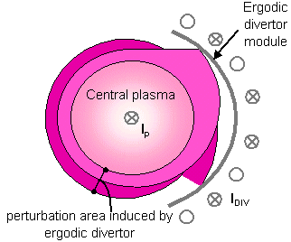
What does this mysterious animal look like? Like 6 modules placed at regular intervals around the chamber, in which a current is allowed to flow to create the perturbation.
The current creating the perturbation (Idiv) flows in the coils shown in black opposite. The magnetic surfaces react by warping near the ergodic divertor module, and the plasma comes into contact with the divertor at the neutralisers.
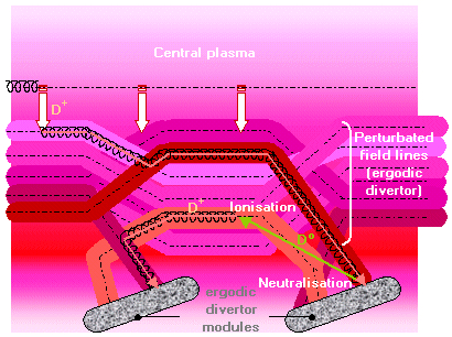
We see opposite a schematic representation of field lines (tubes of different colours) in the edge zone in ergodic divertor configuration, whose modules are shown in red. The field lines are mixed up and, by taking the flow diagram of particles described for the other configurations, we see that the neutral particles are very likely to be ionised again on a field line returning to one of the modules, and thus to stay stuck in an edge zone where the perturbation has an effect.
Plasma-wall interaction and particles and heat extraction
The ergodic divertor: an original configuration tested by Tore Supra over 10 years.
c.The different configurations
The ergodic divertor : the results
Over a period of 10 years Tore Supra has intensively tested the possibilities of the ergodic divertor, which was dismantled in 2000 to start the machine up again in the CIEL configuration with an increased heat extraction capability (incompatibility between the ergodic divertor and the main component of the CIEL project: the toroidal pumped limiter).
The main results obtained are as follows :
good control of the ergodic interference
efficient screening of impurities
strong capability to radiate
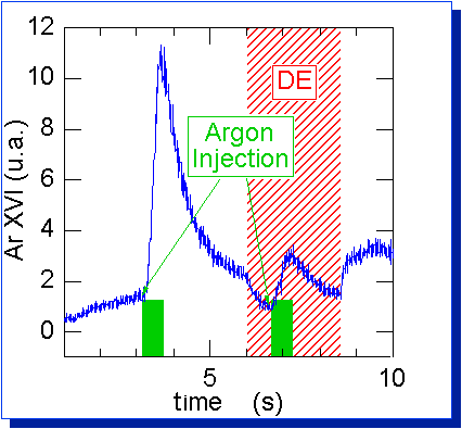
For example, we see here the screening effect of the ergodic divertor on impurities. Two successive identical argon injections are carried out, symbolised in green, one in limiter configuration, and the other with the ergodic divertor activated. We measure in blue the time evolution of the argon signal in the plasma centre. Before injection, the signal is nearly nil, corresponding to traces of argon in the machine. At the moment of injection, the signal soars, then drops, as the argon diffuses towards the plasma edge and is eliminated bit by bit from the centre. It can be seen that during the ergodic divertor phase, the same injection results in a much lower level of argon in the centre. This is the screening efficiency of the ergodic divertor, blocking impurities at the edge.
Analyses are currently being carried out to study the adaptation of an ergodic divertor to a next generation machine (that we imagine for the moment fitted with an axisymetric divertor). In the meanwhile, it is the German machine Textor that will take over study of the ergodic divertor, with the installation of a new device for a new start-up in 2002.
Plasma-wall interaction and particles and heat extraction
How do we manage heat fluxes higher than those on the surface of the sun? By using cutting edge technologies for wall components, and by acting on the plasma to attenuate the thermal load.
d. Heat extraction and radiative scenarios
Plasma edge is harmful.
When the plasma particles follow the field lines and intercept the walls in the edge zone, they deposit their energy, which, even if it is much lower than that encountered in the plasma core, is nevertheless formidable for the solid (1 eV , which is the order og magnitude of the strength of energy binding the atoms). In Tore Supra, we may reach heat fluxes of several tens of MW/m2 along field lines, of the same order as those that reign on the surface of the sun (environ 70 MW/m2). To give an idea of the order of magnitude, 10 MW/m2 falling in 1 second on a simple, not cooled graphite-type carbon surface result in a temperature increase of 1000 °C: we might as well say that nothing can stand up to those conditions !
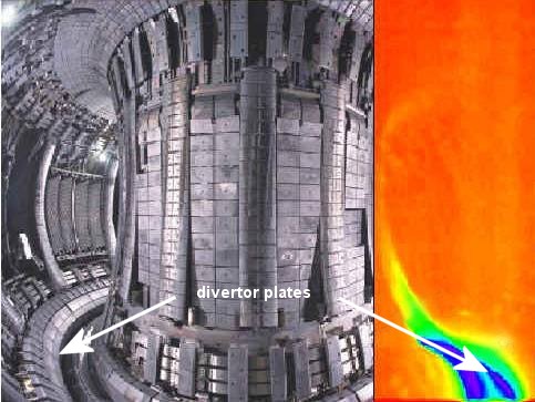
We see here an infrared picture of the JET tokamak, superimposed onto a photograph of the machine, where we clearly observe the heat flow concentrated on the divertor plates (at the bottom in blue).
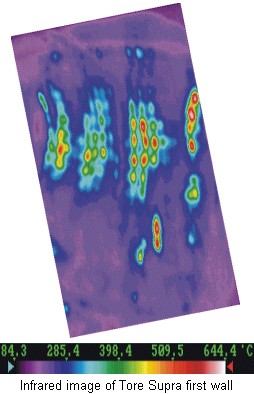
Similarly, the image on the right shows the heat flow on the internal wall of Tore Supra recorded by an infrared camera.
The film below shows the thermal load of the Tore Supra toroidal pumped limiter.
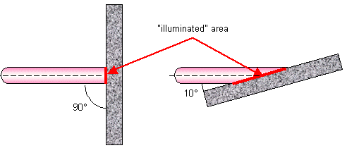
A first idea to lighten the thermal load is to optimise the plasma facing component geometry so as to intercept field lines at a low-angled incidence and spread the incidental flux over as wide a surface as possible. For example, intercepting a field line at an angle of 10° instead of 90° (normal incidence, most constraining situation) attenuates the thermal load by a factor of 6.
The Tore Supra case.
In Tore Supra, a machine intended to operate with long pulses, very particular care has been taken in the design of plasma facing components, which are cooled by a pressurized water flow to be able to withstand intense heat loads for long durations. How are these components designed? Several criteria come into play. First of all, the material facing the plasma. It must withstand thermal shocks, evacuate heat correctly, and not pollute the plasma too much if it is eroded. Carbon, tungsten or beryllium are all suitable candidates. Then, there is the structural material, on which the plasma facing material is assembled and which provides cooling. Here it is heat evacuation that is important, and we usually choose grades of copper in which the cooling pipes are made and in which the water flows under pressure. All that remains is to optimise the thickness of the plasma facing material. If we want to minimise the temperature rise in the component, we must choose the thinnest possible, so that the heat is conducted away as rapidly as possible into the structural material. On the other hand, there must still be a certain solidity, and durability sufficient to withstand erosion by the plasma. Practically speaking, we come to a compromise around a thickness of 1 cm. Progress in the materials used (carbon fibre composite or CFC type, also used in the space industry) and cooling circuit techniques have enabled the development of components capable of withstanding 10 MW/m2 in continuous operation. Tore Supra is an ideal test bench for the technologies and materials developed for the next generation machine (the power injected in the plasma is not as great but falls on a smaller surface as the machine is smaller: the heat fluxes at stake are comparable).
A radiant idea.
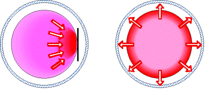
Once the plasma facing component geometry has been optimised, a second idea is to act on the plasma to reduce the heat load: this is what is being researched with radiative scenariosretour, where we try to attenuate the heat flux concentrated on the first component encountered by the plasma by creating a peripheral layer which radiates power uniformly around the machine, thus obtaining a better share of the heat load over all the components.
For example, we see here in the case of a limiter configuration, the heat load concentrated on the first plasma facing component encountered by the field lines in the case of a non-radiative scenario (on the left), whereas in the case of a radiative scenario (on the right), power is spread out over all the walls of the machine, thus resulting in lower heat flows.
Here, we therefore deliberately try to dissipate the power by radiation, but in a well controlled manner. This is obtained either by using the plasma fuel (deuterium) radiation at high density or by injecting a small quantity of a well chosen (for its property) impurity. The difficulty is then to control the radiation layer, both in its intensity (the power balance must not be upset) and its localisation (it must stay at the plasma edge without degrading the central performances) : the impurity must be carefully chosen! Studies have been carried out on Tore Supra and other machines, injecting argon, neon or nitrogen.
A small numerical application
Let us look, for instance, at the orders of magnitude on ITER, the next generation tokamak. There are 300 MW from the plasma core to be evacuated (power produced by the fusion reactions and carried by the alpha particles added to the external power coupled to the plasma). Out of these 300 MW, 100 MW are radiated to the plasma core by different processes (Bremsstrahlung and synchrotron radiation). There are only 200 MW eft which reach the plasma edge, and would be concentrated on the divertor plates, which represent a surface of approximately 10 m² : without radiation, that would give 20 MW/m². Based on studies carried out in the existing machines, radiative scenarios applied to ITER radiate around 150 MW, leaving 50 MW for the divertor (or 5 MW/m², acceptable from a technological point of view) and resulting in heat fluxes of 0.5 MW/m² on the whole machine wall.
Plasma-wall interaction and particles and heat extraction
How do we avoid helium particles, the ashes of the fusion reaction, building up in the discharge and ending up by choking the plasma ? Just get on and pump them out.
e. Extraction and injection of matter
The D-T fusion reactions produce “ashes”, the helium particles. These particles, created in the plasma core, give part of their energy to the plasma through collisions and thus serve to maintain the plasma, before diffusing with the other particles towards the plasma edge. To avoid their concentration to build up, thus eventually chocking the plasma, special devices are implemented on the plasma facing components to extract them. This consists in collecting the ion flux in neutralisation throat designed to guide the neutral flux thus created, insensitive to the effect of the magnetic field, towards a pumping system situated away from the machine.
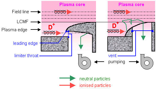
We see here 2 pumping methods experimented on the Tore Supra limiters. The first method consists in directly collecting the ion flux from the limiter throat and guiding it to a pumping system. The advantage: considerable efficiency in pumping, and the drawback: a large flux on the throat leading. A second method consists in letting the incidental ion flux neutralise on the limiter surface, and relying on atomic physics processes to bring back some of the neutrals thus created to the slots leading to the pumping system. The advantage is no more contact leading edge problem, and the drawback is reduced pumping efficiency.
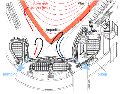
Here we see a cross section of the bottom of the JET tokamak, where the system ensuring the particle extraction is shown. The plasma flux arrives at the edge zone, where it neutralises on the divertor plates. The neutral flux is then collected through chevrons and guided to a pump.
Most present machines work with pure deuterium (JET is the only machine in operation with the necessary installations to work with tritium to date) and extrapolate the results obtained with D-D to D-T fusion. We study helium pumping by injecting helium into the plasma from the outside and by observing how the pumping system behaves. The performances attained are compatible with the requirements of a future reactor (helium concentration in the plasma centre less than 10%).
It is unfortunately difficult to preferentially evacuate the helium at the plasma edge. We thus extract everything that comes from it, a mixture of fuel (deuterium and tritium), ash (helium) and a low proportion of impurities emitted by the machine walls. This mixture is then sorted out, the helium and impurities are eliminated, and we continuously re-inject fuel to compensate for what has been extracted from the discharge. The pumping system is therefore destined not only to extract ash in the future reactor, but also to control the plasma fuel density in present machines, by acting on the extracted and injected quantities.
Nevertheless, in addition to these so-called “active” pumping systems there is a so-called “passive” pumping retour , due to the wall. Indeed, carbon, a material very often chosen for plasma facing components on account of its strong resistance to thermal shock and its low atomic number reducing of radiation problems, has a very specific property: it is a real hydrogen sponge, capable of absorbing a large part of the flux of incidental particles, until the material becomes saturated. It may then spit out particles that it has absorbed, particularly in the case of overheating. The wall is thus to be reckoned with, when we try to control the plasma density.
As for plasma supply, we have three means of fuel injection retour into the plasma :
injection of gas from a pipe arriving in the vacuum chamber. Easy to set up, this method is not very efficient but very commonly used on tokamaks (typically 20% of the injected particles penetrate into the plasma on Tore Supra)
neutral injection, which also serves as heating system. The efficiency is greater, but the quantities injected are small and are not always enough to supply the plasma.
ice pellets injection, which consists of injecting tiny deuterium or tritium pellets in the form of ice. We use systems that look like compressed air pistols, capable of injecting deuterium pellets at several kilometres per second. The device is complex, but results in much better plasma filling performance than gas injection (reaching efficiencies up to 80% on Tore Supra). Developments are in progress to adapt current pulsed systems towards continuous operation.
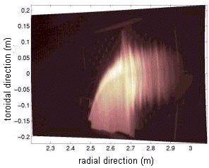
The image opposite represents injection of a pellet into Tore Supra seen from above, detected by a camera sensitive to the radiation of neutral deuterium. The halo corresponds to a very dense cloud of neutral particles surrounding the pellet, which “melts” in the course of its path within the plasma, spreading its contents, which ionise (and then become invisible to the camera) on the magnetic surfaces that it crosses.
Plasma-wall interaction and particles and heat extraction
What happens when the plasma interacts with the wall? Let us take another look, this time from the point of view of the wall.
f. And the wall in all this?
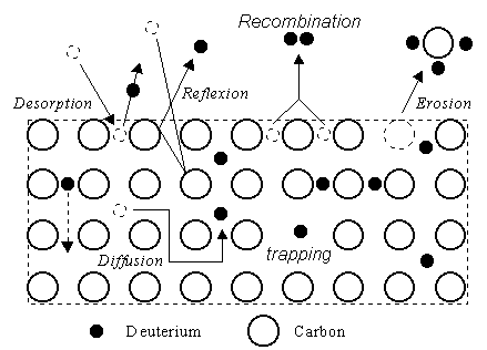
What happens when the plasma interacts with a solid wall ? Let us take the case where the wall is made of carbon, a very common material in tokamaks on account of its resistance to thermal shocks, and the incidental particle a D+ Deuterium ion. A number of phenomena may take place.
Reflection
First of all, the incidental charged particle may simply be reflected in the form of a neutral particle (D atom or D2 molecule in the case of recombination) and go back to the plasma, where it will once again be ionised. This is recycling.
Absorption, retention
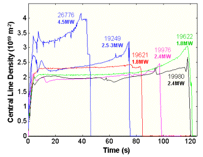
Subsequently, the particle may be absorbed by the wall, as carbon acts like a sponge for hydrogen. This goes on until the carbon is saturated with hydrogen, just as a sponge may only absorb a certain amount of water. Under certain conditions (overheating for example), the wall may also release particles that it has trapped, like a sponge being squeezed. The incident particles may also by impact free trapped particles (desorption). All this complicates the control of the plasma density, which may be strongly influenced by the state of saturation of the wall, a huge reservoir of particles with a very long filling duration. This was clearly seen on Tore Supra, in particular in the long pulse programme, where the plasma density tends to rise at the end of the pulse, probably on account of gas emission from a far-away wall, which is not concerned in shorter pulses but heats up over time. The solution is cooling down all wall components, even those further away from the plasma. This is what was done on Tore Supra in the framework of the CIEL project.
Tokamak conditioning
In addition, we are also developing conditioning retour techniques of the vacuum chamber, in order to better control the wall status. The first procedure consists in covering the walls with a very fine protective coating with special properties. In Tore Supra, we periodically (around once a month) carry out a boronisation procedure (film in boron carbide), which has in addition the advantage of being an oxygen trap thus enhancing plasma purity. Between two boronisations, we can also desaturate the wall with glow discharge (i.e. we create a very low power helium plasma without the confinement field, which cleans the walls and gets out the deuterium trapped by impact of helium particles on the wall). This is carried out at night to prepare the experimental programme for the next day. Finally, during an experimental day, we have set up conditioning discharges so as to help recover some of the trapped particles and operate with a wall that is more or less de-saturated, even after a number of discharges or a disruption.
Apart from the control of plasma density, another important question is the hydrogen retention in the wall, which will become problematic when we use radioactive tritium as fuel in the next step. From the results of the tokamaks JET and TFTR, the only machines to have used tritium up to now, we are elaborating scenarios that will minimise retention in the wall, as well as conditioning techniques to recover trapped tritium.
Erosion
Finally, the incident particles may tear out carbon atoms from the wall, a process that is known as erosion. Some of these impurity atoms may then, as a result of a several atomic physical phenomena, get through to the centre of the discharges and damage the central plasma performance by radiating part of the power coupled to the plasma. After complex transport phenomena, the eroded carbon may be deposited on the walls of the machine, sometimes quite a long away from the place it was eroded from. But this replacement is not enough to prevent slow erosion of plasma facing components, in particular in places where there is a concentration of incidental particle flux: this is one of the main preoccupations for next generation machines, where the components must be ensured a sufficiently long lifetime to not have to be changed too frequently. Many studies are being carried out, as much from the wall point of view (doped materials to better withstand erosion, use of tungsten or of beryllium instead of carbon) as from the plasma point of view (attenuation of incidental flux in radiative scenarios).
Long pulses: Tore Supra is heading for the future reactor
Tore Supra, the only large machine in the world fitted with supra-conducting magnets, providing a permanent toroidal magnetic field, has become the champion of the study of long pulses, taking a step at a time towards steady state, indispensable for the reactor.
Indeed, the time scales of the different physical phenomena at stake in a fusion machine are very varied, going from less than a millisecond for the stability of magnetic equilibrium (MHD) to a matter of minutes for plasma-wall equilibrium and even hours for erosion
A machine like Tore Supra, enabling exploration of long pulses of several minutes, is thus complementary to a machine like JET, very effective, but limited to a pulse duration of a few seconds.
It may be seen on the diagram opposite, where we have represented the characteristics of most of the present machines in terms of fusion performance (the triple product density/ confinement time/temperature of the Lawson criterion) as a function of the discharge duration. Full in symbols represent performances already attained, empty symbols show expected performances for machines at project stage (like the next step of ITER) or improvements on existing machines (like Tore Supra with the CIMES project of extending its heating system).
JET is not far off expected fusion performances for the next step of ITER whereas Tore Supra (TS for the initiated) is getting closer to the required durations. Thus, while JET is galloping ahead like a racehorse, Tore Supra is continuing its endurance work and is just as indispensable.
Long pulses: a speciality of Tore Supra
Tore Supra opens the path to the continuous regime of the reactor, with its discharge record of 2 min. How is this performance achieved?
What recipe is needed to achieve a long pulse? A number of parameters come into play. First of all, the magnetic configuration : a system is needed to allow for continuous confinement of particles (supra-conducting magnet for the toroidal magnetic field, non inductive current generation using hybrid frequency heating for the poloidal magnetic field). Then, power and matter injection: heating systems and particles plasma supply working over long periods are needed. And then, of course, as a corollary, the power and matter extraction : plasma facing components cooled by flow water are needed, capable of withstanding enormous heat continuously without excessive temperature rise, while evacuating particles. Then, the plasma parameters must be well chosen (magnetic field, plasma current, density and so on), so that the magnetic equilibrium is stable, the coupling of heating to plasma is satisfactory, the efficiency of current generation optimal and the plasma facing components do not overheat. All this must be monitored in real time thanks to efficient diagnostics in order to be able to intervene on control systems if necessary (magnets, heating, gas injection and so on).
The integration of cutting edge technology and the latest breakthroughs in plasma physics has enabled Tore Supra to achieve the world record of energy injected into a tokamak with 280 MJ in a 2 minutes discharge.
To go further and thus enrich the database, which is used to scale the next step ITER, Tore Supra is now aiming at a performance of 25 MW injected for 1000 seconds (or 25 GJ). At this stage, it will only be one order of magnitude down from ITER in terms of energy (intended for 200 GJ) and will achieve the same pulse duration (1000 s). Moreover, even if the coupled power in Tore Supra is lower, the power density (i.e. the power divided by the surface collecting it) attained on plasma facing components is comparable, the machine being smaller. This is therefore the opportunity for real life testing of next step technologies.
To be up to these ambitious goals, Tore Supra has undergone a facelift:
first of all, its plasma facing components have been renovated, so as to be capable of extracting heat and particles continuously up to running at 20 MW (CIEL project, standing for ” Internal Components and Limiter”). The new components have been installed on the machine, which started again in August 2001 in this configuration (cf re-starting Tore Supra).
then, its heating and matter injecting systems are in the course of upgrading, to be capable of injecting the desired power into the machine and continuously supply the plasma with particles (CIMES project for “Components for Injection of Matter and Stable Energy “).
We see here the last preparatory measures to start up Tore Supra again in the CIEL configuration. The operator is working in white overalls to minimise the introduction of impurities into the machine. We see at the bottom of the picture the main plasma facing component, intended to evacuate most of the power and extract the particles, the CIEL start-up limiter (LDC) pending the arrival of the definitive limiter (LPT) for 2002. In the foreground on the left are the carbon safety rings, placed on the stainless steel inner wall. Finally, on the right we can see openings in the wall, enabling access to the plasma for diagnostics or the introduction of the heating antennae.
In 2001, Tore Supra starts again in a totally new configuration, with a CIEL start-up limiter (LDC) enabling tests of the plasma facing component technology. In 2002, the whole CIEL project will be up and running, with the pumped toroidal limiter (LPT): the machine will then be ready to extract 25 MW continuously, all ready to break the GJ record. In parallel, progress in heating systems is still being made, with the first stage CIMES1, which, with the enhancement of the hybrid system, will help along the path to even longer pulses.
Diagnostics
How do we know what is happening in the plasma core, in a machine hermetically sealed in a vacuum with temperatures of several million degrees? This is the role of diagnostics, measuring instruments that are as diverse as they are clever, requiring the know-how of a great number of specialists. Tokamaks are full of them, as they are quite indispensable…
What do we want to measure?
We can divide the characteristics to be measured into three main categories:
We want to know how to place the machine in terms of the triple product density/ confinement time,/temperature, the deciding factor for fusion based on Lawson criterion.
Knowing, often in real time, what is happening at the level of the machine control parameters (magnetic field, plasma current etc) helps programme the following discharge in advance according to scientists’ requirements, and even to act in the course of a discharge to correct any possible problem. These diagnostics are vital to the proper working of the tokamak.
We are constantly seeking better comprehension of a great number of complex physical phenomena governing the plasma in the tokamak. Some experimental parameters are directly accessible thanks to diagnostics, but others have to be deduced from measurements using more or less sophisticated models, which may range from an simple formula to a computer code needing hours of calculation on extremely powerful computers. For example, to analyse heat transport phenomena, we can measure what was injected into the machine (ohmic power and additional power) and what was extracted in the different instrument equipped components properly instrumented. We can then deduce the distribution between losses by radiation and conduction/convection, and we can then trace back to the transport coefficients thanks to numerical codes.
X rays, measured by cameras fitted with special detectors, are linked to the radiation from the slowing down of very energetic electrons, and provide information about their distribution in energy and thus heating efficiency, for example.
In the ultraviolet, spectrometers measure radiation from heavy impurities, like metals, providing information on the plasma pollution and possibly setting off warning alarms in the event of a component overheating.
CCD visible light cameras give a general view of the vacuum chamber, with the pink halo characteristic of the plasma to wall interaction on the edge of the discharge.
Still in visible light, optic fibres or endoscopes installed on plasma facing components give local information on radiation from light elements, like deuterium, helium or carbon. This enables progress in understanding of plasma-wall interactions, particularly as regards emission of impurities by erosion.
Here is for example a close-up of a neutraliser of the ergodic divertor (the plasma is resting on the long structures in the middle of the picture), and the same thing, seen by an endoscope fitted with a filter to select emission of a hydrocarbon molecule , formed from eroded carbon and deuterium in the plasma from certain erosion processes. It can be clearly seen that emission is concentrated on the surfaces with which the plasma enters into contact.
As for infra-rouge, many cameras are used to measure the increase in temperature of plasma facing components, and represent a vital tool for the safety of the machine. If we notice an unusual occurrence of overheating, we immediately cut off the additional power, and stop the plasma
Like in the air or in water waves may propagate in plasma, with notably the possibility of heating by coupling it to a well-chosen frequency. But waves are also precious measuring instruments and many diagnostics are based on principles close to those of radar or sonar: we send a wave, we detect a response from the environment through which it passes , and we make deductions about the environment.
For example, in reflectometry, we use the reflecting property of a family of waves at a given cut-off frequency. This cut-off frequency is linked to the plasma density encountered, and by measuring the time the wave takes to go and come back once it has been reflected (transmitter and receiver are placed in the same place), we can deduce the profile of density in the plasma.
We see here a density profile, measured by the reflectometer along the major radius of the machine (3.2 m corresponds to the plasma edge, on the outside of the torus) and its time evolution. Around t = 6 secs, we move the plasma by several centimetres towards the inside of the machine, clearly recorded by the reflectometer.
In interferometry, we use a wave capable of crossing the plasma (transmitter and receiver are placed on the two sides of the machine) and we measure the difference in phase and polarisation between the incident wavel and the wave collected after crossing the plasma, giving information both on the density and current profile. Thomson scattering uses the same kind of technique with a slightly different wave to deduce the temperature profile. There are also diagnostics capable of measuring density fluctuations, connected with plasma turbulence.
We can also place a probe in the edge plasma, as long as it is properly protected. Thus many components in the vacuum vessel are fitted with Langmuir probes, small robust elements made of carbon which collect the plasma current, providing information on local density and temperature. If you take a good look at the photograph of the ergodic divertor neutraliser opposite, you will see 4 Langmuir probes inserted between the neutraliser structures. Tore Supra is also equipped with a mobile probe, which is capable of going in and exploring the first few centimetres of the edge plasma thanks to an arm that puts in and then immediately withdraws the diagnostic, before the plasma has time to damage it.
Finally, the machine is also fitted with a number of other more conventional diagnostics, which are not reserved to plasmas, as for example pressure gauges to check the vacuum quality or assess pumping performance, magnetic measurement coils to characterise the plasma magnetic configuration and its MHD activity, or thermocouples to measure temperature increases in the cooling circuits and carry out a balance of the power taken out of machine.
We also measure the neutrons produced by fusion reactions. In the case of Tore Supra, the only fuel used is deuterium. The D-D fusion products neutron and tritium. This tritium may then react with the plasma deuterium to create D-T fusion, which also products neutrons. These neutrons are detected by highly reactive sensors.
performance
control of the machine
comprehension of physics
How do we measure what we cannot touch ?
It is obviously difficult to put a measuring instrument into the plasma, a rather hostile environment with its millions of degrees. This is very well expressed in the words of an English lord, following a question from one of his colleagues during a debate on construction of the tokamak JET, who asked “But what sort of thermometer is able to measure a million degrees?” The lord replied, “A big one, I presume”. We have then to resort to measuring instruments that observe the plasma from a respectable distance, often behind specially designed windows. It is impossible to be exhaustive (Tore Supra has more than 40 diagnostics) but we can mention a few and classify them into different categories according to the principle of measurement:
using the plasma natural emission in the entire wavelength, from x rays to infrared, through visible light.
probe the response of the plasma to wave propagation
placing a diagnostic in the vacuum chamber
And then the more conventional…
How do we use the diagnostics to control the machine: servo-control
In addition to their measurement function, certain diagnostics are used to control the discharge. They therefore have to send back their data in real time, requiring very high performance electronic components.
For example, a servo-control commonly used, is that on gas injection, in order to attain a given density. Indeed, the gas injection necessary to obtain a given density is not easy to determine in advance. It depends on the chosen scenario (for instance, if the ergodic divertor is activated with its screening properties, a much stronger injection will be needed than in the limiter configuration to achieve the same density) and the state of the wall (if the wall is very well de-saturated, it will retain a high proportion of the injected deuterium and a high injection will be thus needed; on the other hand, if it is near to saturation and starts to release particles, a more modest injection will be needed). In the beginning we thus programme a “moderate” injection depending on the density we wish to obtain, then we use density measuring by interferometer density measurements to open the gas injection valve to a greater or lesser degree during the discharge. If the measurement is above the target density, we close the valve, if it is below, we open it up.
These servo-controls are be very useful, in particular in cases where we explore delicate operations, which easily tend to lead to disruption, like the high radiative scenarios, high power coupling or long pulses.
A common day in the life of Tore Supra
Beyond the purely scientific aspect, everyday life around Tore Supra is also a human adventure, as in all great physics research tools. Come in and share a physicist everyday life with all its ups and downs
Imagine that you are a physicist in the Department of Research on Controlled Fusion. Your specialist area is refining scenarios with the goal of achieving long pulses. Today you are the physicist in charge and it is up to you to decide what the day programme is on the Tore Supra tokamak. Your duty is to beat the record of energy injected into the machine, with long well-performing discharges. The goal to be reached is to get to 300 MJ, with 4-5 MW of power in a 60 to 70 seconds discharge (a little reminder: energy is equal to power multiplied by the time during which it is applied, so you have to manage to use a lot of MW on long durations).
It is a risky programme, and the machine must be pushed to the limit. To help you, you have a whole team around you. First of all there is the pilot. He is the one at the controls of the machine, who carries out the programme that you carefully set out in advance. He is a key figure and like a sort of sea captain, he is the only master on board after God. Then there is the head of computing, whom you can rely on in the event of a system control or command problem or a problem of data acquisition. And, of course, everything is computerised on Tore Supra (or nearly everything), which is crucial to success. Then come all the people in charge of diagnostics and other sub-systems that you need for your day to go well. And finally there are the other physicists interested in the day’s schedule, each with his or her own speciality. Quite a few people around in the control room, what do you think?
It is 8 o’clock, and the day is off to a start. The vacuum chamber has been conditioned by a series of glow discharge during the night so that the wall is well de-saturated. The heavy doors have been closed on the tore hall, and the toroidal field is on. After a short briefing with the day team to make sure everything is ready, we get warmed up with a first ohmic starting pulse, just to get a feel for the machine. The countdown starts. The screens light up and there is the plasma, all pink through the lens of the visible camera. A good start-up, but the wall seems overloaded despite conditioning, so we will have to adjust the gas injection into the vacuum chamber.
The plasma leaning on the first inner wall, seen by a visible camera through a machine port. We can see the tiles making up the wall, and the pink halo characteristic of the plasma edge, radiating at this wavelength.
After this promising beginning, we get on with more serious matters like starting the additional heating. We are counting on the hybrid power to generate the current and lengthen the time of the discharge by taking over from the conventional transformer, and on the FCI heating to inject power as a complement to the hybrid. The scenario is delicate, as operating conditions must be found which suit both systems, each of which naturally has contradictory requirements. The hybrid current generation efficiency increases with decreasing density. On the other hand, FCI heating does not manage to couple power to the plasma below a certain density. Following calculation code simulations and previously acquired experience, we therefore go for an intermediate density. Let us hope that the gas injection system manages to control the situation and maintain stable density, above all if the wall has decided to act up.
The systems must be powered up progressively, to be properly conditioned. We successively test the two hybrid couplers, as well as the two FCI antennae. 0.5 MW, 1 MW, no problem at 2 MW, a few breakdowns but nothing serious. We took the precaution of finely adjusting the systems in position and frequency. These discharges dedicated to increasing the additional power last half a minute, cruising speed for Tore Supra. Between two discharges , twenty minutes are required, the time for all diagnostics to get their results checked into a computer database. And here comes the computer failure, data from the hybrid system have not come up. The head of computing deals with it. Conclusion is that data from the discharges has been definitively lost, even if the system is up and ready for the next run. The FCI antennae are working properly, coupling is good, despite their position way back from the plasma, necessary so as not to let them get too hot on long runs. On the other hand, things are not as good for the hybrid system: only one coupler is usable, and we cannot take it up above 1.8 MW without breakdown and nickel emission into the plasma. We will have to make do with what we have.
Things are getting worse: the following run disrupts on a fault in the poloidal. The teams in charge of this sub-system get busy to find the origin of the breakdown. During this time, a conditioning discharge is carried out to get the wall back to scratch. Towards 11:30 everything is back to normal and the day can carry on. Both heating systems start up again well, 2 MW for the FCI, 1.6 MW for the hybrid. The clean out seems to have had its effect, with the wall doing its job a bit more effectively, so we will have to inject strongly to achieve the desired density. The discharge duration is lengthened to 35 seconds. The density tends to take off after twenty or so seconds, but remains acceptable. 38 seconds, 40 seconds, 42 seconds, and 46 seconds: the rise in density seems to have calmed down. We are up to 177 MJ, not bad at all.
On the following run, a rise in impurities at 16 secs and then a disruption. An UFO (Unidentified Flying Object), as we say in Tore Supra jargon, went by the cameras. The spectroscopists have detected iron, nickel and copper in the plasma. Not a good sign! Probably a plasma facing component overheating. The plasma was leaning on the first internal wall: the infrared camera detected no problem on the carbon tiles, but it could not see the whole chamber. The antenna protections are coming under strain, but there again the infrared surveillance cameras saw nothing abnormal. We have a meeting to decide what to do next in the programme. In the meantime, we launch a conditioning run to recover from disruption. Finally, with the agreement of the pilot, we get going again: to ease up on the FCI antennae, we use 2 at the same time out of 3, and alternate every 4 seconds, …..high wire stuff. What is more, we add a modulation on the vertical plasma position, to move the point of impact of the plasma on the wall and thus avoid excessive heating.
It is not easy getting started again. Each time the discharge disrupts. We make more conditioning discharges. In the end we get going: 184 MJ, 194 MJ, 200 MJ. The machine is not easy to pilot, often nearing disruption, density rises at the end of the discharge, but we progress bit by bit. The pilot is prudent, knowing that a slightly too strong disruption will put an end to things for the day. At 19:45, we give it everything we have got for the last discharge: one minute with power of 4 MW. We managed it!
The outcome of the day: the ambitious goal of 300 MJ was not reached, on account of a faulty hybrid coupler, which limited the power that could be injected into the machine. On the other hand, on the antennae that could be used coupling was very satisfactory. The original scenario developed for this programme, simultaneously requiring the two types of heating, is thus validated. In addition, the modulation of the plasma in vertical position turned out to be effective. With all that, a pulse of a minute at 240 MJ was attained (N°26776 !), coming close to the absolute record of the machine (280 MJ with 2 MW for two minutes).
Time evolution of density for several discharge from Tore Supra long pulse database, including discharge N°26776 carried out today. We can easily see here the problem of the increase in density over long periods, which should be solved by the CIEL project, in which the whole of the machine is cooled. Final answer with the resumption of the CIEL configuration, in autumn 2001 !
Post-scriptum: it turns out after analysis that the rise in impurities was due to a burst pump tube at the top of the machine, not in the field of view of the cameras, probably inflicted by a beam of electrons accelerated by the hybrid. There is nothing serious, but we will just have to avoid putting strain on it while waiting for repair when the machine is open again.